|
|
Post by dubiousgolfer on Oct 23, 2019 11:30:05 GMT -5
S, You wrote-: " Otherwise, you can place your double pendulum device on the ground and tug one of the segments horizontally in the direction that the segment lies. The untouched segment will rotate to align with the segment you tugged. A circular path for tugging is not required for the distal segment to rotate." I tried your experiment by first adopting a 90 degree angle between the two segments (L-shape arrangement between the two segments) with the proximal segment aligned perpendicular to my body and the peripheral segment aligned to the right at a 90 degree angle relative to the proximal segment - and I noted that the peripheral segment did not rotate if I tugged on the proximal segment in a leftwards direction in such a manner that the central and distal ends of the proximal segment moved at the same speed, which caused the hinge joint to move in a straight line manner in a leftwards direction. I could only get the the peripheral segment to rotate if I pulled the distal end of the proximal segment leftwards while keeping the central end of the proximal segment fixed in position. Under those conditions, the hinge joint moved leftwards, but in an arced (circular) manner. That experiment supports my opinion that the hinge joint must transcribe a circular path to induce the release in a double pendulum swing model. Watch the following video between the 1:17 -1:30 minute time points, and note that the peripheral segment does not rotate when the hinge joint moves in a straight line manner. Jeff. Dr Mann It might be worthwhile repeating that experiment but adding some mass to the end of that peripheral segment . The reason you didn't seem to see much rotation of that peripheral segment when you pulled the proximal segment laterally leftwards is because the COM of that L shaped flail is pretty close to the line of your leftwards pulling force vector. By adding some mass to the end of that peripheral segment will move the COM further away from tail end of that pulling leftwards force vector. Once you have added that extra mass and repeat the experiment , you should find that the peripheral segment will rotate and align itself with your pulling force (ie. in line with the proximal segment). DG |
|
|
|
Post by imperfectgolfer on Oct 23, 2019 11:57:52 GMT -5
S, You wrote-: " Otherwise, you can place your double pendulum device on the ground and tug one of the segments horizontally in the direction that the segment lies. The untouched segment will rotate to align with the segment you tugged. A circular path for tugging is not required for the distal segment to rotate." I tried your experiment by first adopting a 90 degree angle between the two segments (L-shape arrangement between the two segments) with the proximal segment aligned perpendicular to my body and the peripheral segment aligned to the right at a 90 degree angle relative to the proximal segment - and I noted that the peripheral segment did not rotate if I tugged on the proximal segment in a leftwards direction in such a manner that the central and distal ends of the proximal segment moved at the same speed, which caused the hinge joint to move in a straight line manner in a leftwards direction. I could only get the the peripheral segment to rotate if I pulled the distal end of the proximal segment leftwards while keeping the central end of the proximal segment fixed in position. Under those conditions, the hinge joint moved leftwards, but in an arced (circular) manner. That experiment supports my opinion that the hinge joint must transcribe a circular path to induce the release in a double pendulum swing model. Watch the following video between the 1:17 -1:30 minute time points, and note that the peripheral segment does not rotate when the hinge joint moves in a straight line manner. Jeff. Dr Mann It might be worthwhile repeating that experiment but adding some mass to the end of that peripheral segment . The reason you didn't seem to see much rotation of that peripheral segment when you pulled the proximal segment laterally leftwards is because the COM of that L shaped flail is pretty close to the line of your leftwards pulling force vector. By adding some mass to the end of that peripheral segment will move the COM further away from tail end of that pulling leftwards force vector. Once you have added that extra mass and repeat the experiment , you should find that the peripheral segment will rotate and align itself with your pulling force (ie. in line with the proximal segment). DG DG, I taped two AA batteries to the distal end of the peripheral segment to increase the mass at the distal end of the peripheral segment and I then repeated the experiment. It made no difference and the periperal segment did not rotate! If the direction of pull of the hinge joint is in a straight-line-alignment with the longitudinal axis of the peripheral segment, increasing the mass of the distal end of the segment makes no difference. I can only get the peripheral segment to rotate if the pulling force exerted by motion of the hinge joint is out-of-aligment with the longitudinal axis of the peripheral segment. Jeff. |
|
|
|
Post by imperfectgolfer on Oct 23, 2019 12:57:27 GMT -5
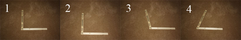
Here is the result of a new experiment that I performed. I placed my double pendulum model on my wheat-colored carpeted floor so that the proximal segment is parallel to the base of my tripod (and the bottom of the image). I then angled the peripheral segment so that it is at a right-angle to the proximal segment and at a right angle to the bottom of the image - see image 1. I then pulled the proximal segment towards the base of my tripod (towards the bottom of the image) so that the hinge joint moved at right angles to the bottom of the image in a straight line manner and where that straight line motion is along the longitudinal axis of the peripheral segment. Note that the peripheral segment remains at a right angle relative to the proximal segment and it does not angulate (rotate) - see image 2.
I then repeated the experiment by pulling the proximal segment in a rightwards direction so that the hinge joint moved parallel to the bottom of the image. Note that the peripheral segment angulates and rotates anti-clockwise to align itself with the proximal segment - see image 3. I then repeated the experiment by pushing the proximal segment to the left so that the hinge joint moves leftwards, but parallel to the bottom of the image. Now, the peripheral segment angulates in the opposite direction and rotates clockwise, so that the angle between the proximal and peripheral segments becomes more acute as the peripheral segment tries to align itself with the proximal segment (in an opposite directional manner) - see image 4. I think that this experiment demonstrates that the peripheral segment will only angulate (rotate) if the hinge joint moves out-of-aligment with the longitudinal axis of the peripheral segment and that the direction of rotation depends on the direction of motion of the hinge joint. Relative to the COM of the distal end of the peripheral segment, the hinge joint is moving anti-clockwise in image 3 and clockwise in image 4. I think that image 3 represents what happens during the release of PA#2 during a golf swing action - the left wrist moves out-of-aligment with respect to the COM of the club by moving in an anti-clockwise direction as the left hand moves more targetwards after P5.5 (end of the "straightish" section of the hand arc path).
Jeff.
|
|
|
|
Post by dubiousgolfer on Oct 23, 2019 16:58:42 GMT -5
Dr Mann
Yes , all your above tests is exactly what I expected to happen according to the Laws Of Physics.
So doesn't 'image 3' experiment confirm what Syllogist said in his previous posts below?
"A double pendulum as you created in the video you just posted does not require circular motion for the upper segment to seek to align 180 degrees with the lower segment. If, from a face-on view, you held the double pendulum in the shape of an L and then tugged the lower segment purely horizontally rightward, then the upper segment would move downward and leftward, seeking alignment with the lower segment."
"Otherwise, you can place your double pendulum device on the ground and tug one of the segments horizontally in the direction that the segment lies. The untouched segment will rotate to align with the segment you tugged. A circular path for tugging is not required for the distal segment to rotate."
DG
|
|
|
|
Post by imperfectgolfer on Oct 23, 2019 17:22:38 GMT -5
Dr Mann Yes , all your above tests is exactly what I expected to happen according to the Laws Of Physics. So doesn't 'image 3' experiment confirm what Syllogist said in his previous posts below? "A double pendulum as you created in the video you just posted does not require circular motion for the upper segment to seek to align 180 degrees with the lower segment. If, from a face-on view, you held the double pendulum in the shape of an L and then tugged the lower segment purely horizontally rightward, then the upper segment would move downward and leftward, seeking alignment with the lower segment." "Otherwise, you can place your double pendulum device on the ground and tug one of the segments horizontally in the direction that the segment lies. The untouched segment will rotate to align with the segment you tugged. A circular path for tugging is not required for the distal segment to rotate." DG DG,
You asked-: "So doesn't 'image 3' experiment confirm what Syllogist said in his previous posts below?"
"A double pendulum as you created in the video you just posted does not require circular motion for the upper segment to seek to align 180 degrees with the lower segment.". No!
There only two potential motions of the hinge joint relative to the COM of the peripheral segment - a straight line motion and a curved (=circular) motion. A straight line motion of the hinge joint happens in image 2 when the hinge joint moves away in a direction that is straight-in-line with the longitudinal axis of the peripheral segment, while a curved (circular) motion happens in image 3 and 4 when the hinge joint moves away in a direction that is out-of-alignment with respect to the longitudinal axis of the peripheral segment. Any out-of-line motion of the hinge joint can be correctly classified as a curved (circular motion).
Jeff.
|
|
|
|
Post by dubiousgolfer on Oct 23, 2019 17:57:16 GMT -5
Dr Mann "Any out-of-line motion of the hinge joint can be correctly classified as a curved (circular motion)" Is the above a TGM definition as I've never heard it before? When I look at image 3 below where I've drawn a red arrow to represent the 'tugging' to the right , I would normally define that as a straight line path and not curved.  DG |
|
|
|
Post by imperfectgolfer on Oct 23, 2019 22:30:36 GMT -5
Dr Mann "Any out-of-line motion of the hinge joint can be correctly classified as a curved (circular motion)" Is the above a TGM definition as I've never heard it before? When I look at image 3 below where I've drawn a red arrow to represent the 'tugging' to the right , I would normally define that as a straight line path and not curved. DG DG, I agree that the motion of the hinge joint in image 2 and image 3 are both in a straight line direction. After further thought, I now think that my experiment was a waste of time and effort. In image 3, the peripheral segment is not really releasing where the peripheral segment is acquiring angular momentum due to the hinge arc path being out-of-alignment relative to the peripheral segment's COM. What is really happening is that the proximal end of the peripheral segment is being pulled to the right because the hinge joint is moving rightwards while the distal end of the peripheral segment is not moving as much due to frictional resistance against the carpet. The change in the angle between the two segments from 90 degrees to a more obstuse angle is due to this phenomenon and it is not due to a "release phenomenon". I now think that this irrelevant type of experimental demonstration has nothing to do with the PA#2 release phenomenon that happens in a "real life" golf swing action and it is a distraction of no relevance. Jeff. |
|
|
|
Post by syllogist on Oct 24, 2019 7:30:25 GMT -5
Dr. Mann,
I'm not so sure that the demonstration is not applicable, although I was trying to show in a different manner parametric acceleration via Miura's vertical tug concept at release.
It seems to me that the force of the movement of the peripheral segment acts on the hinge (hands) in a real golf swing.
If, in a real golf down swing, the arms were able to suddenly change direction from vertical downward to horizontal, the speed of the release would be much greater than arms that travel in a more circular direction. The reason why Miura's "inward pull" is of little consequence is because the arms/hands cannot abruptly change direction during release.
S
|
|
|
|
Post by dubiousgolfer on Oct 24, 2019 16:17:30 GMT -5
Whatever the theoretical physics and forces (through the club handle) that may be responsible for release , one thing is for certain , hand speed and path is directly related to the release of PA#2 in a swinging action.
DG
|
|
|
|
Post by imperfectgolfer on Oct 27, 2019 12:34:49 GMT -5
More Malaska stupidity - part 3.
Look at the latest BeBetterGolf video featuring Brendon and Mike Malaska.
In this video, MM is trying teach BD to hit the ball higher - by varying the degree of shaft lean at impact by using a "hand feel" technique (a "feel" of varying the clubshaft's degree of shaft lean at impact with a hand manipulation technique).
If you watch the video, you can note how inconsistent BD is with respect to his ball flight trajectory, which is not surprising considering the fact that he is trying to time a hand manipulation technique when the clubhead is traveling at a very fast speed near impact. This MM-inspired hand manipulation technique used to vary ball flight trajectory is as stupid as the AJ Bonar hand cross over release technique that AJ Bonar tried to teach Brendon in the following BeBetterGolf videos.
AJ Bonar thinks that you can selectively and reliably hit draws and fades by using his hand crossover manipulation technique.
I think that any hand manipulation technique near impact is a very unreliable golf swing technique for controlling either ball flight trajectory or ball flight side-spin.
Regarding the most optimum technique of driving the ball with higher launch in a reliably consistent manner, I think that is much better to use the combination of i) ball position relative to low point + ii) body/left arm alignments at impact - and one should not attempt to manipulate the hands through impact.
Jeff.
|
|
|
|
Post by utahgolfer on Oct 27, 2019 14:24:11 GMT -5
Jeff,
It is obvious that hand manipulation at impact can change ball flight patterns...higher, lower, left, and right. No disputing this. However, as you stated, the real key is consistency. Some players with elite hand eye coordination are certainly better at hand manipulation than the average golfer, and this may be one reason some golfers, like Bubba Watson, use it, but it is a recipe for disaster for most golfers. Instructors, like MM and AJB, need to better understand the drive hold release and its many benefits, and teach it as the standard best way to swing through impact for most golfers. And, then teach or allow other acceptable release patterns as exceptions to the standard drive hold release pattern.imho
Also, I liked the earlier discussion about the release of pa#2, but can you expand on DG's summary that we know hand speed and path are directly related to the release of pa#2. I assume the hand path is the most important and should be curvilinear to promote an optimal release of pa#2 and that hand speed must be modulated to match the curve of the path, and that hand speed is slowing relative to club head after p6 as pa#2 is optimally released. Is this correct?
UG
|
|
|
|
Post by imperfectgolfer on Oct 27, 2019 14:54:53 GMT -5
Jeff, It is obvious that hand manipulation at impact can change ball flight patterns...higher, lower, left, and right. No disputing this. However, as you stated, the real key is consistency. Some players with elite hand eye coordination are certainly better at hand manipulation than the average golfer, and this may be one reason some golfers, like Bubba Watson, use it, but it is a recipe for disaster for most golfers. Instructors, like MM and AJB, need to better understand the drive hold release and its many benefits, and teach it as the standard best way to swing through impact for most golfers. And, then teach or allow other acceptable release patterns as exceptions to the standard drive hold release pattern.imho Also, I liked the earlier discussion about the release of pa#2, but can you expand on DG's summary that we know hand speed and path are directly related to the release of pa#2. I assume the hand path is the most important and should be curvilinear to promote an optimal release of pa#2 and that hand speed must be modulated to match the curve of the path, and that hand speed is slowing relative to club head after p6 as pa#2 is optimally released. Is this correct? UG I agree with your bold-highlighted statements. For a driver swing, a "tight curvilinear" hand arc path between P5.5 and P6.2 is advantageous in order to increase the speed of release of PA#2, but the hand speed during that time period, and also between P6.2 and impact, must be compatible with the speed of release of PA#2 so that the clubhead speed and hand speed are optimally matched in order for the clubshaft to catch-up to the hands by impact with the desired amount of clubshaft lean at impact. Maintaining an intact LFFW/GFLW during the P5.5 => P7.2+ time period, without trying to independently flip-or-roll the hands using a hand manipulation maneuver, is likely to be a more controllable swing technique in terms of reliably controlling the clubhead path and clubface ROC through impact.
Jeff.
|
|
|
|
Post by syllogist on Oct 28, 2019 6:06:56 GMT -5
 Dr. Mann, I found it difficult to direct my attention to his seemingly incessant babble so I took a few moments to find a still photo of the master himself. Perhaps his crossover takes some time to complete.  S Attachments:
|
|